stm32F411RE Configuration Steps:
Configuration of RCC (Clock Control Register):
To start programming on the stm32F303RE microcontroller and with any ST microcontroller, everything needed must be enabled first through the RCC reg.
this can be done by derefrencing the RCC using (->) and choosing the needed peripherals or buses and this can be achieved by using the archeticture of the controller.
for example, if we want to enable Port A of the general purpose input and outputs(GPIOs), the chosen bus is AHBENR (AHB Peripheral clock enable register) and the code can be written like this:
RCC->AHBENR |= (1< < (the bit needed))
Configuration of GPIOs:
First, configuration of the pin modes. this includes four modes and can be choosen throught the bit value in the port mode register (GPIOx_MODER). Each pin on the port has 2 bits in the GPIOx_MODER.
these four modes are:
- Input mode (reset state) at bit value 00
- General purpose output mode at bit value 01
- Alternate function mode at bit value 10
- Analog at bit value 11

After this according to your preference if the pin is configured as an output pin , we will use the port output type register(GPIOx_OTYPER). This register will determine whether the pin
uses:
- Output Push/Pull at bit value 0
- Output open-drain at bit value 1

Then we have to specify the speed of this output pin. To do that we will use the GPIO output speed register(GPIOx_OSPEEDR). It can be configured by:
- Low speed at bit value x0 where x is 0 or 1 doesn't matter.
- Medium speed at bit value 01
- High speed at bit value 11

At the end we will specify if the pin is pull up or down assuming it's configured to do so from the port output type register:
- No pull up,pull down at bit value 00
- pull up at bit value 01
- pull down at bit value 10

UART Initialization:
UART initialization starts with knowing which UART peripheral in the stm32 chip is going to be used.
First, the ABPENR1 or ABPENR2 as deictated by the selected UART but each bus has runs on a different clock frequency where ABPENR1 runs on 72MHz and ABPENR2 runs on 32MHz.
then, it's time to enable the UART in the ABPENR register. In this project USART2 is used which is found on ABPENR2 bus and so it's bit in the ABPENR2 is set to high with the same method used to enable the GPIO ports.
After that, we enable the GPIO port that contains the Tx and Rx pins of the UART. These pins are PA2 and PA3 respectively.
lastly, PA2 and PA3 are configured as alternate function pins by putting the value 1,0 in the corresponding pins in the MODER register, then 0 in the OTYPER register and as high speed in the OSPEEDR register.
Now, the alternate function of the pins should be selected. This is done by configuring the AFR (Alternate Function Register).
this register is divided into two register AFRL (low) and AFRH(high).
each pin is has 16 alternate function that is multiplexed into 4 bits.
Since we are using PA2 and PA3, we will configure them in the AFRL register. To select them as Tx and Rx, the AFRL is set to AF7 value which is 0111 in binary in bits 8,9,10,11 and 12,13,14,15.

Baudrate Selection:
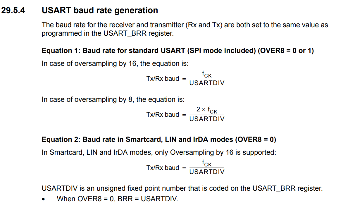
The UART protocol is asynchronous and doesn't use a clock to receive and send the data so it relays on the baudrate. to select the baudrate we first need to know about the oversampling concept.
The receiver must sample the incoming data stream at a rate that is higher than the bit rate to determine when each bit starts and ends 1. Oversampling is used to increase the sampling rate and improve the accuracy of the sampling process.Usually, the oversampling is set to be 16 using the OVER8 and setting it to 0 in the UART Control Register 1(USART_CR1).
to select the baudrate we desire ,9600 in this project, we divide the Fck value of the ABPENR selected bus which is the ABPENR2 on the baudrate desired (9600) and then putting the result as a value of hexadecimal in the USART_BRR register(Baud Rate Register).In this project the value is 0xEA6.

Now, we can enable the pins to send or receive data by setting the bits UE(UART Enable), TE (Transmit Enable),RE(Receive Enable)in the USART_CR1 and then, we can start using the UART just without interrupts yet.

Notice: The BRR value should be set before setting the UART Enable bit (UE) in the USART_CR1.
This function shows how to initialize the UART6:
UART_INIT(void){

RCC->APB2ENR |= RCC_APB2ENR_USART6EN;                //USART2 TX=PA2 ,RX=PA3

RCC->AHB1ENR |= RCC_AHB1ENR_GPIOCEN;                 //Enable port A in the RCC reg


// configuring PA2 and PA3 to AF pinmode
GPIOC->MODER |= GPIO_MODER_MODER6_1 ;
GPIOC->MODER &=~ GPIO_MODER_MODER6_0;
GPIOC->MODER |= GPIO_MODER_MODER7_1 ;
GPIOC->MODER &=~ GPIO_MODER_MODER7_0;

GPIOC->OTYPER &=~ GPIO_OTYPER_OT_6;       //PA2 set to push_pull No_PULL by default
GPIOC->OTYPER &=~ GPIO_OTYPER_OT_7;       //PA3 set to push_pull No_PULL by default

//set speed of PA2,PA3 to high speed
GPIOC->OSPEEDR |= GPIO_OSPEEDER_OSPEEDR6 | GPIO_OSPEEDER_OSPEEDR7 ;

GPIOC->AFR[0] &=~ (1<<24) | (1<<25) | (1<<26) | (1<<28) | (1<<29) | (1<<30); //PA2 , PA3 alternate function AF7 USART2

GPIOC->AFR[0] |=(1<<27) | (1<<31);


// set baud rate before setting bit UE(UART Enable) to 1 and start sending or receiving

// oversampling form bit OVER8 = 0 is 16 by default
USART6->BRR= 0x28B0; // for APB1 36MHz at baud rate 9600

//----------|  UART Enable  |Receive Enable|Transmit Enable
USART6->CR1 |= USART_CR1_UE | USART_CR1_RE | USART_CR1_TE;
}
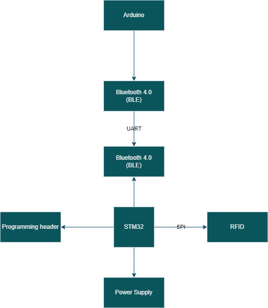
Block Diagram:
Circuit Design:
to be updated
PCB Layout:
to be updated
Manufacturing:
to be updated
Firmware:
to be updated
Testing:
to be updated