Objective
The function of the circuit is to make a dice with LEDS and a couple of ICs
Components
1 555 timer ic
1 Voltage regulator 7805
2 10uf capacitor
1 100 uf capacitor
1 1k,10k resistor
7 LEDs
1 Counter 74LS93N ic
Jumpers
Battery or any voltage source with more than 7v
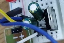
Step 1:
Start by connecting the voltage regulator circuit as shown. After this step you should have a constant 5 voltage from the voltage regulator. Don't forget to make a common ground
.jpeg)
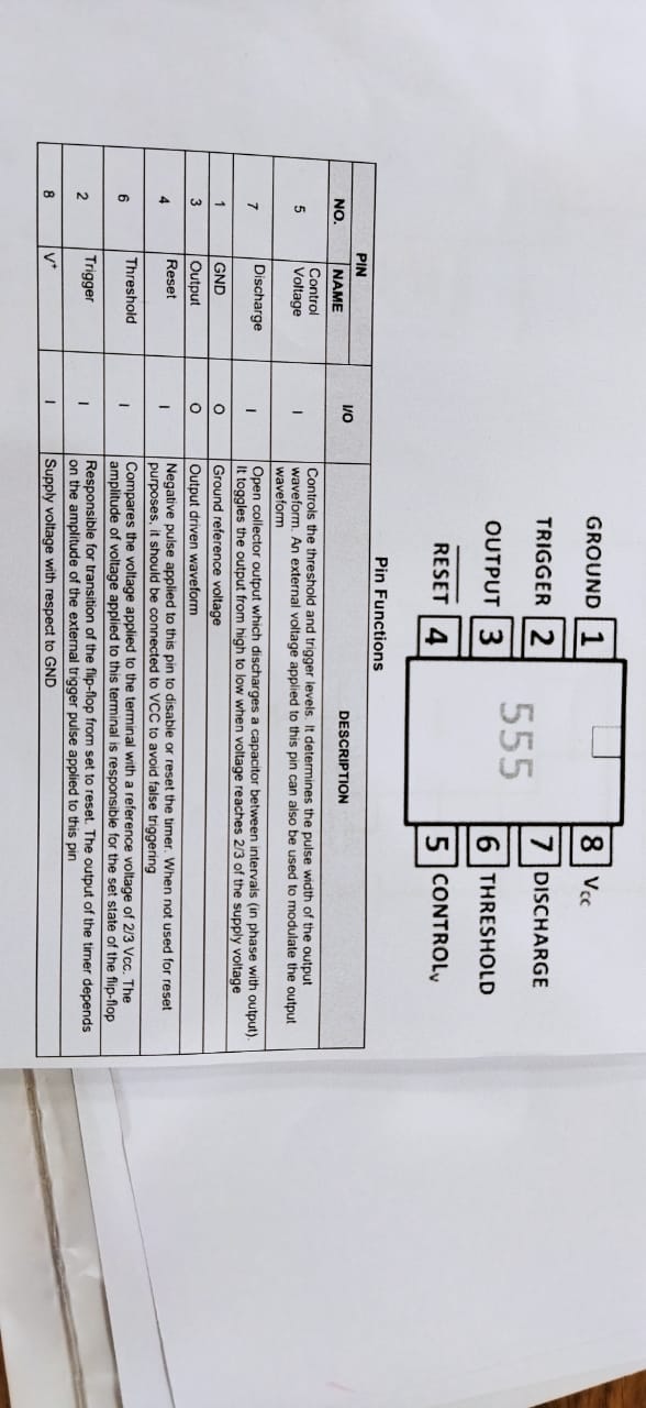
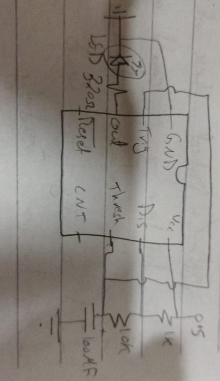
Step 2:
Now start connecting the 555 timer. The 555 timer is used to create a signal that is similar to a clock. And this could be done by the following connection. By changing any of the values of the resistors or the capacitor this would effect the frequancy of the output. To understand the function of each pin look at the pin describtion below.
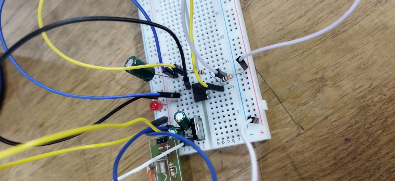
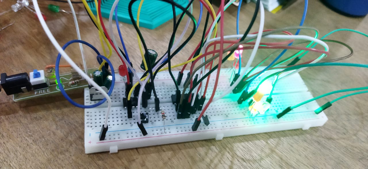
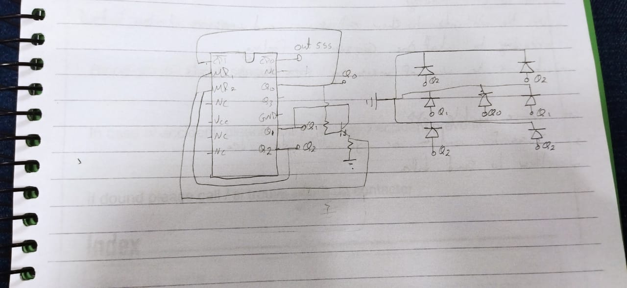
Step 3:
Now after connecting the timer we have an output that is similar to a clock. This output is then used as the clock for the counter ic. The connection of this is below in the images. From the name of the ic we can deduce what its function is. When the clock sends a signal the counter increases. And we can read the counter from the outputs Q0~Q3. Now comes the challenge, which is how to use this outputs to create a dice with LEDs. First we will only use 3 outputs as this will create 8 possibilities (Q0,Q1,Q2). Then we can use this pins and connect them in a certain way that each output is responsible for switching on certain LEDs to create a number. Q0 lights on number 1, Q1 lights on number 2, Q2 lights on number 4. To light on any other number of the dice then we just use the combination of this blocks.After connecting the LEDs we need to add a button between the Vcc of the 555 timer and the +5 volt, this button stops the counter and shows a random number when pressed. (Make change the 1k and 10k resistor combination in the 555 connection with just 1k resistor in order to increase the frequancy). The following images shows the connections in detial.
.jpeg)