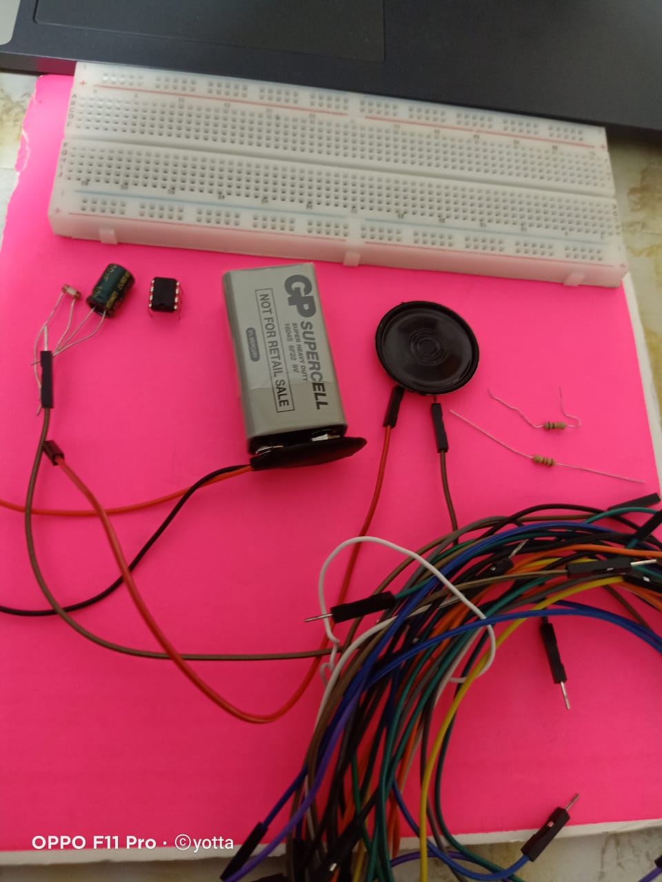
components :
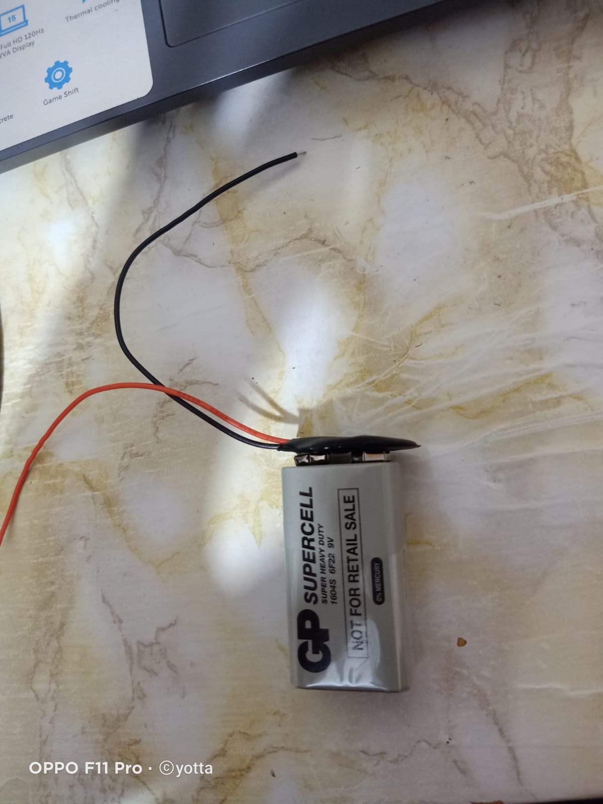
1 9V Battery
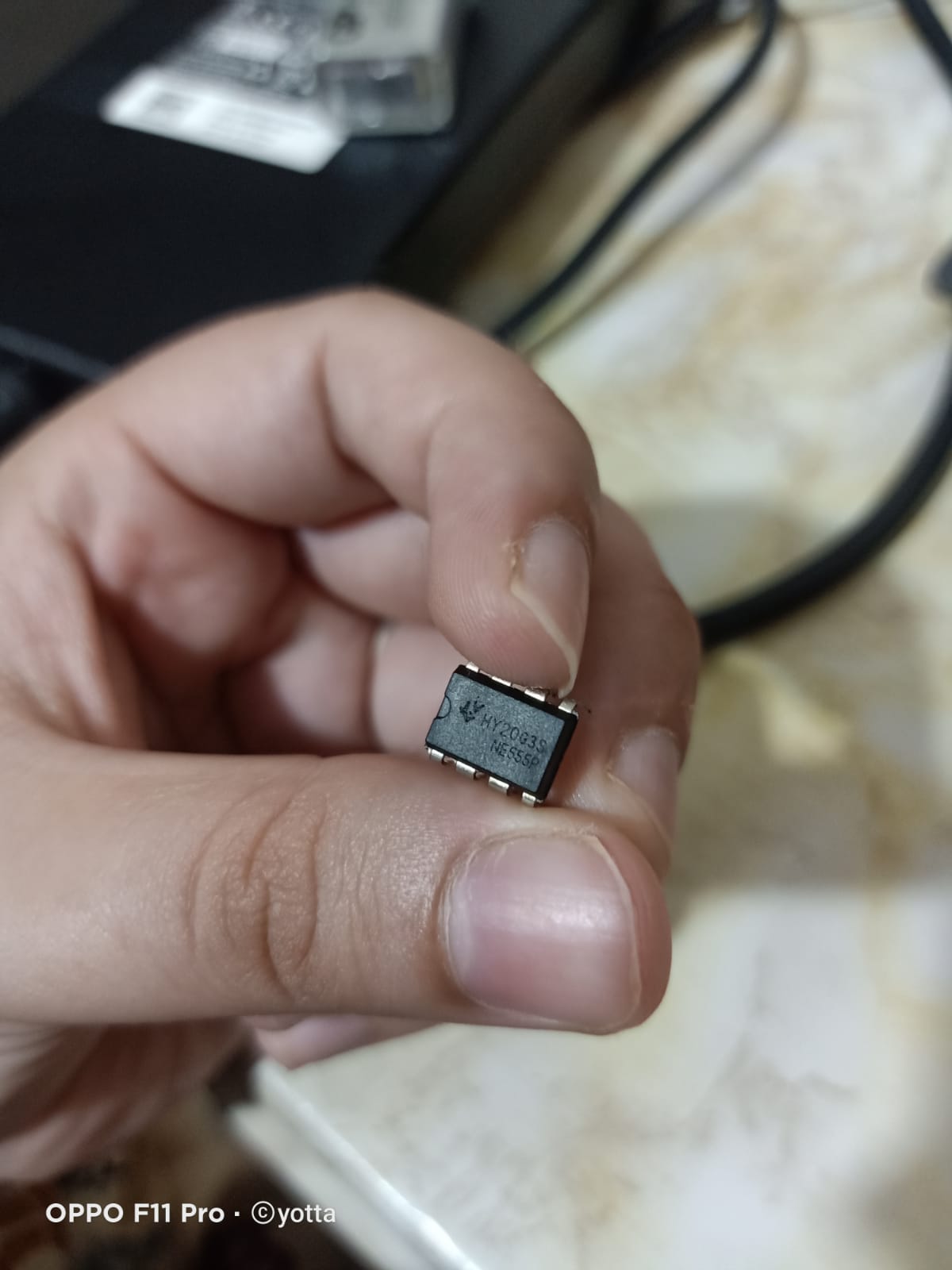
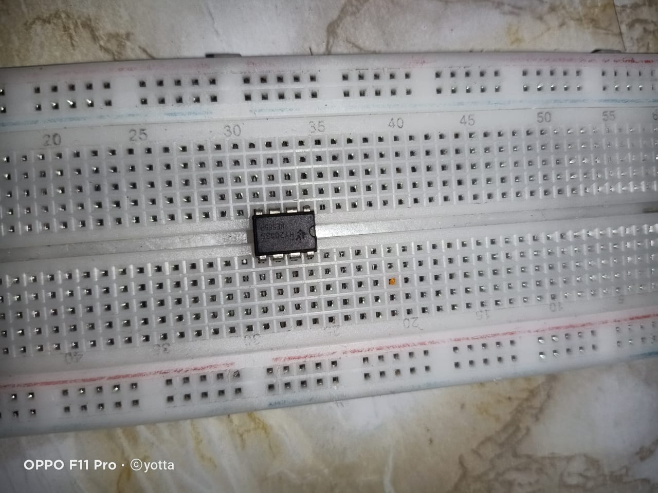
1 555 timer ic
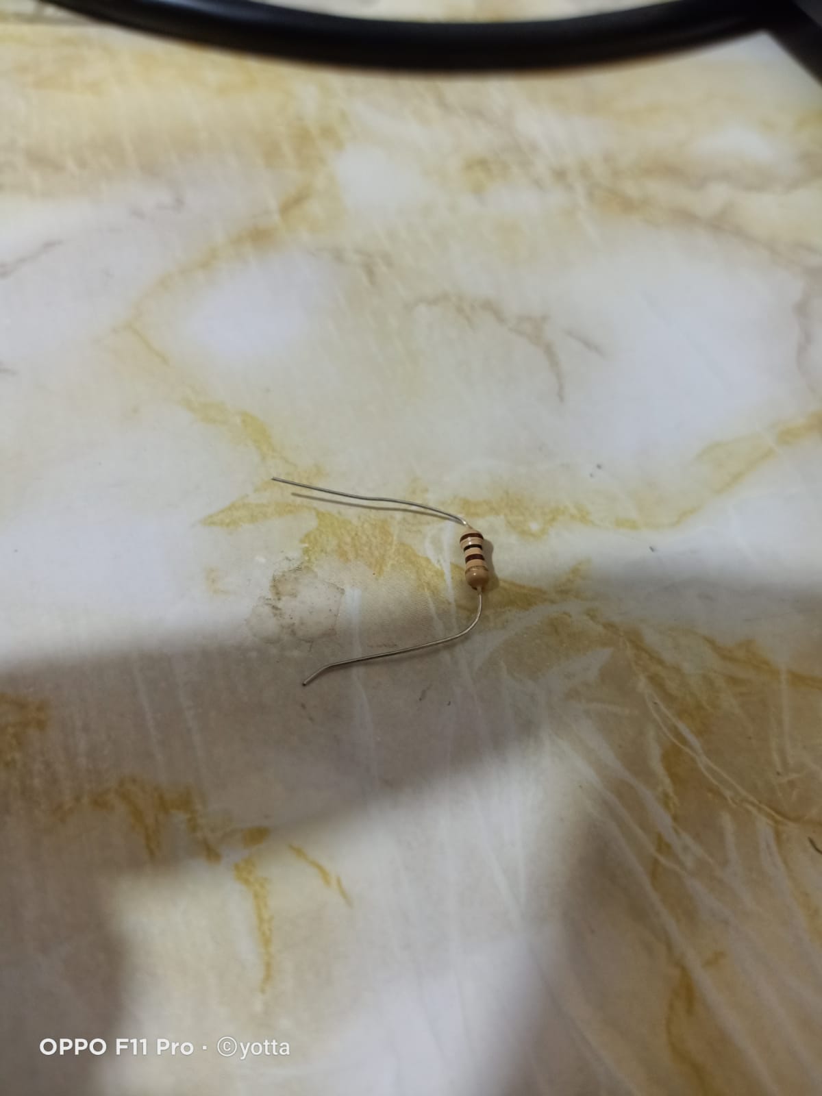
1 2.2KΩ resistor
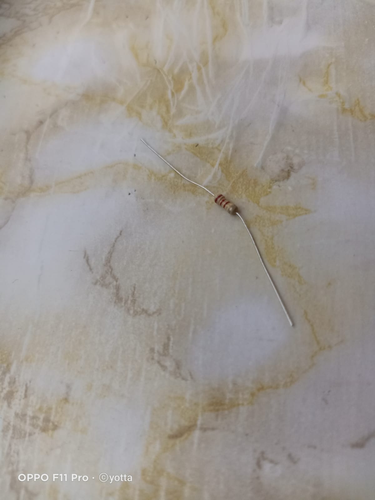
1 10Ω resistor
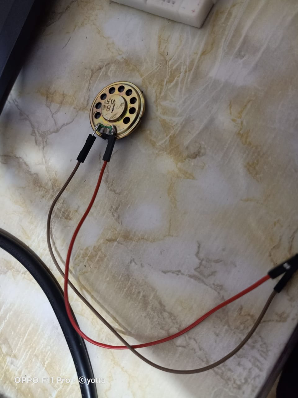
1 8Ω Speaker
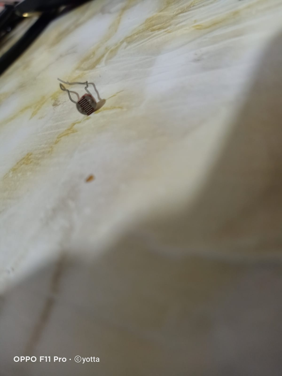
1 Photoresistor1
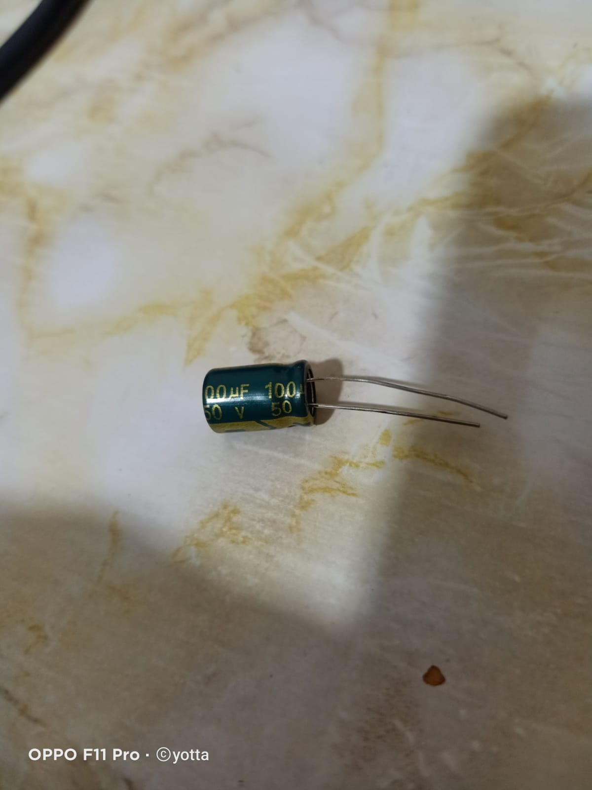
1 100μF electrolytic Capacitor
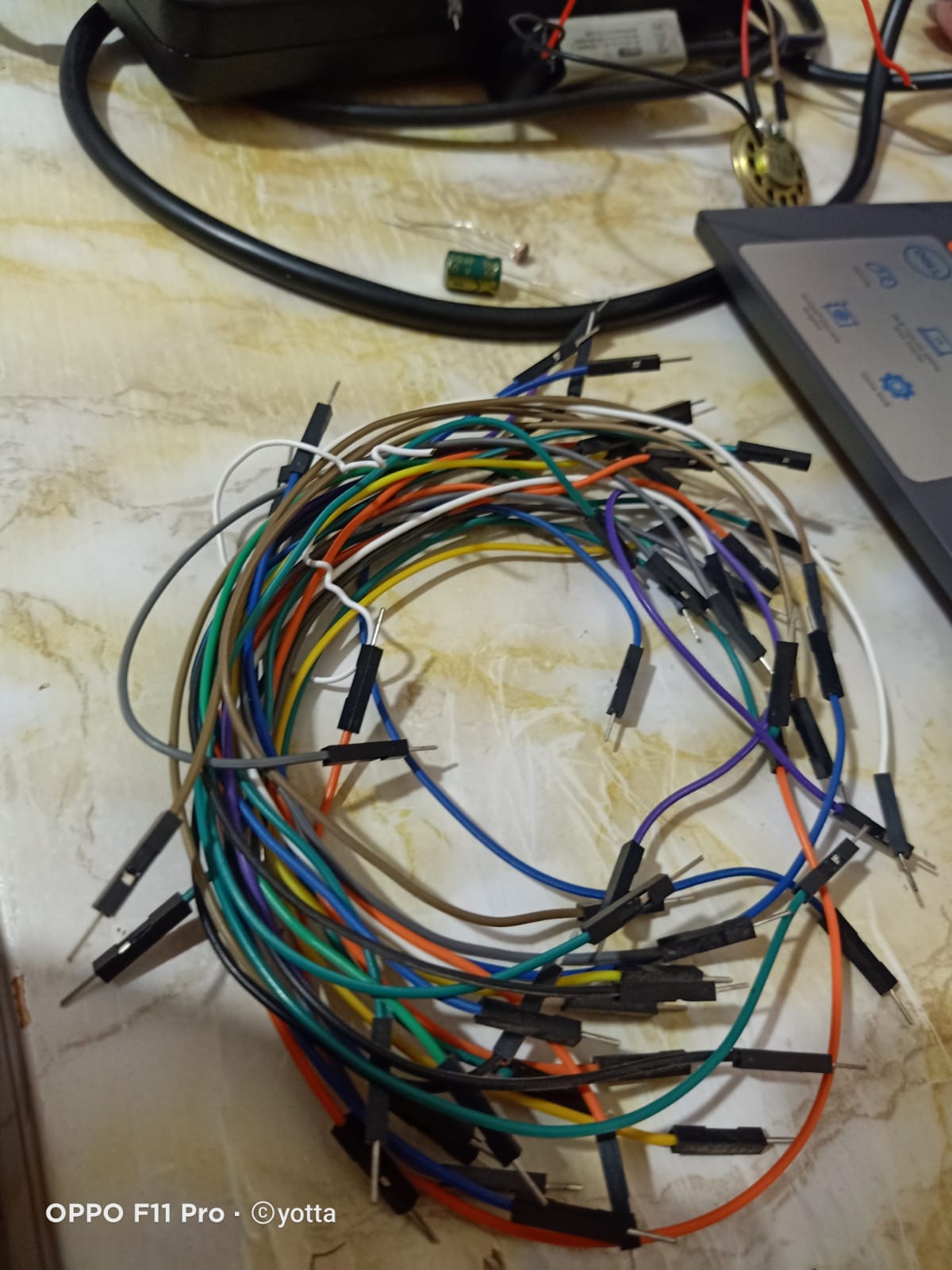
Jumper wires
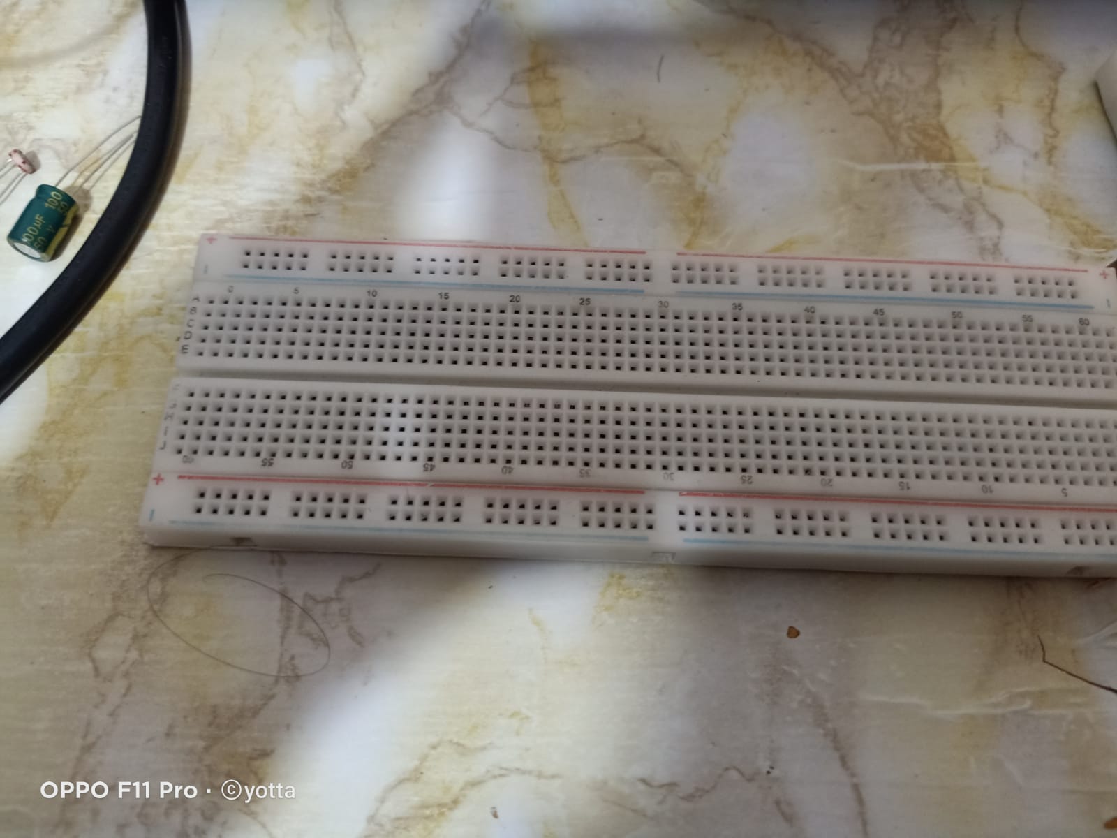
bread board
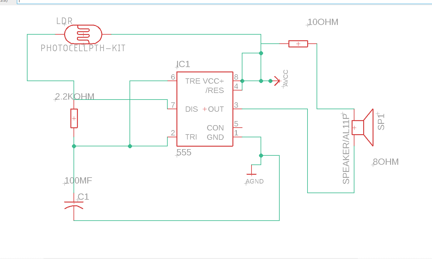
Step 1:
sketch on eagle
Step 2:
SEARCH ABOUT THE IC
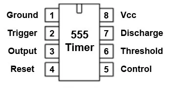
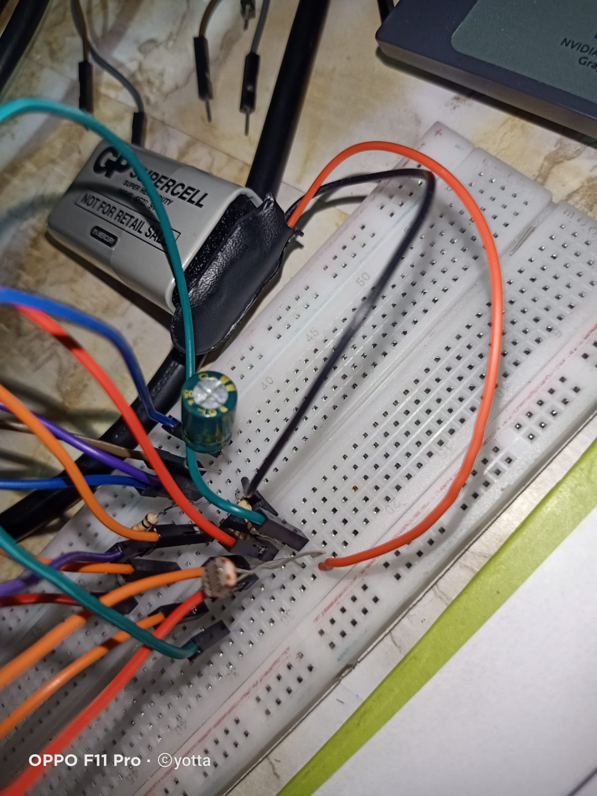
Step 3:
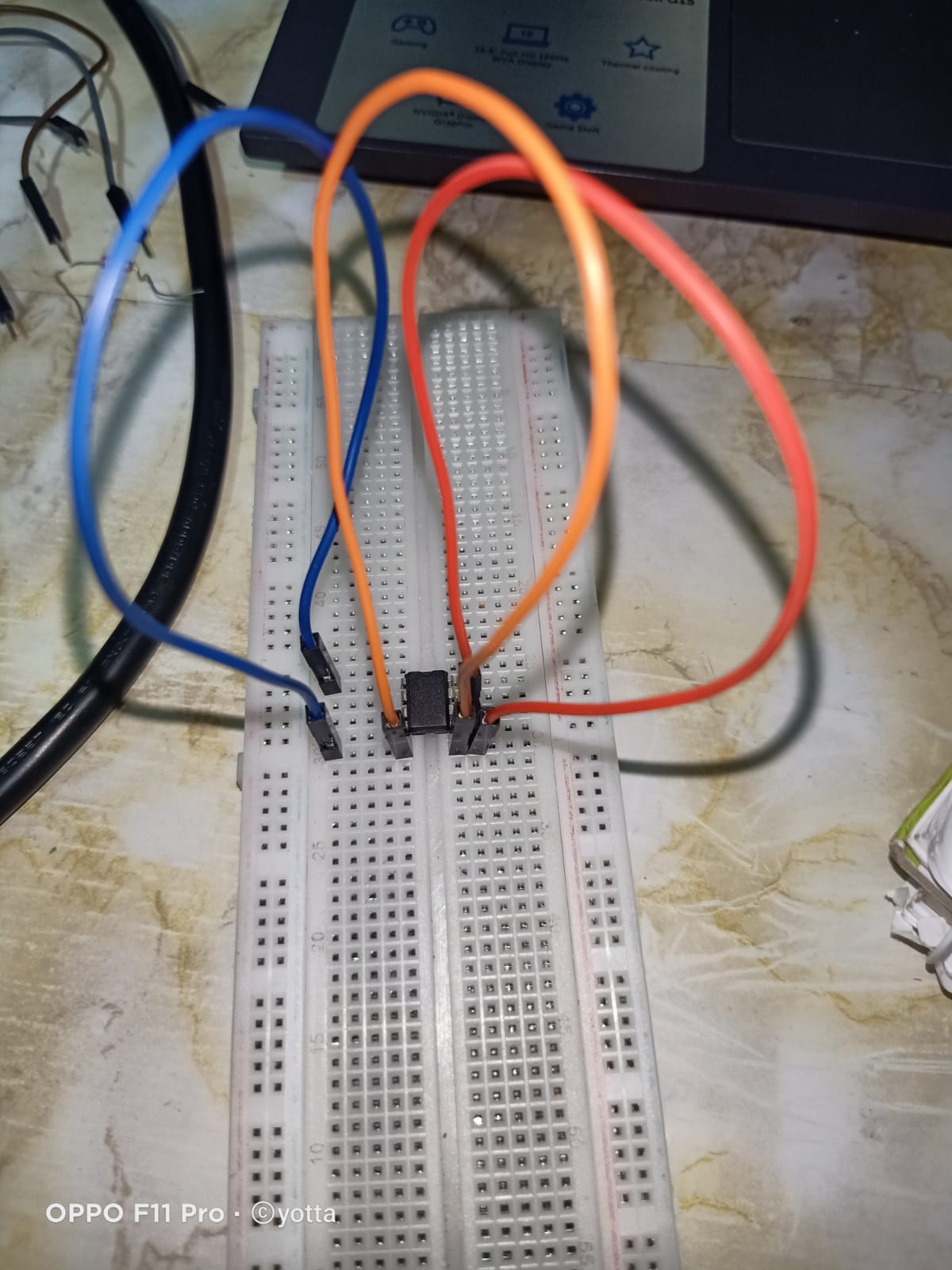
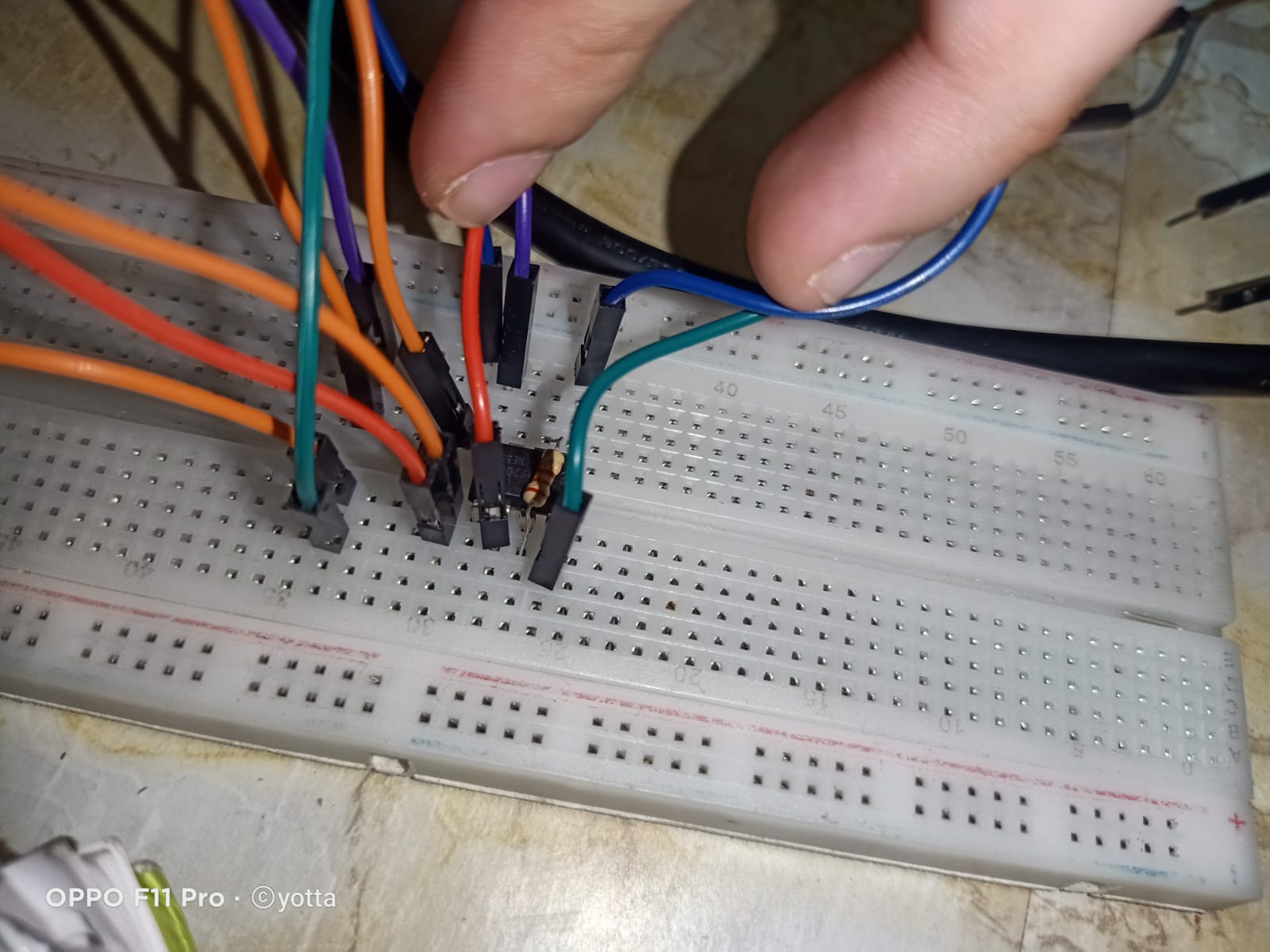
START CONNECTING :
Step 4:
connect the two parts of the breadboard
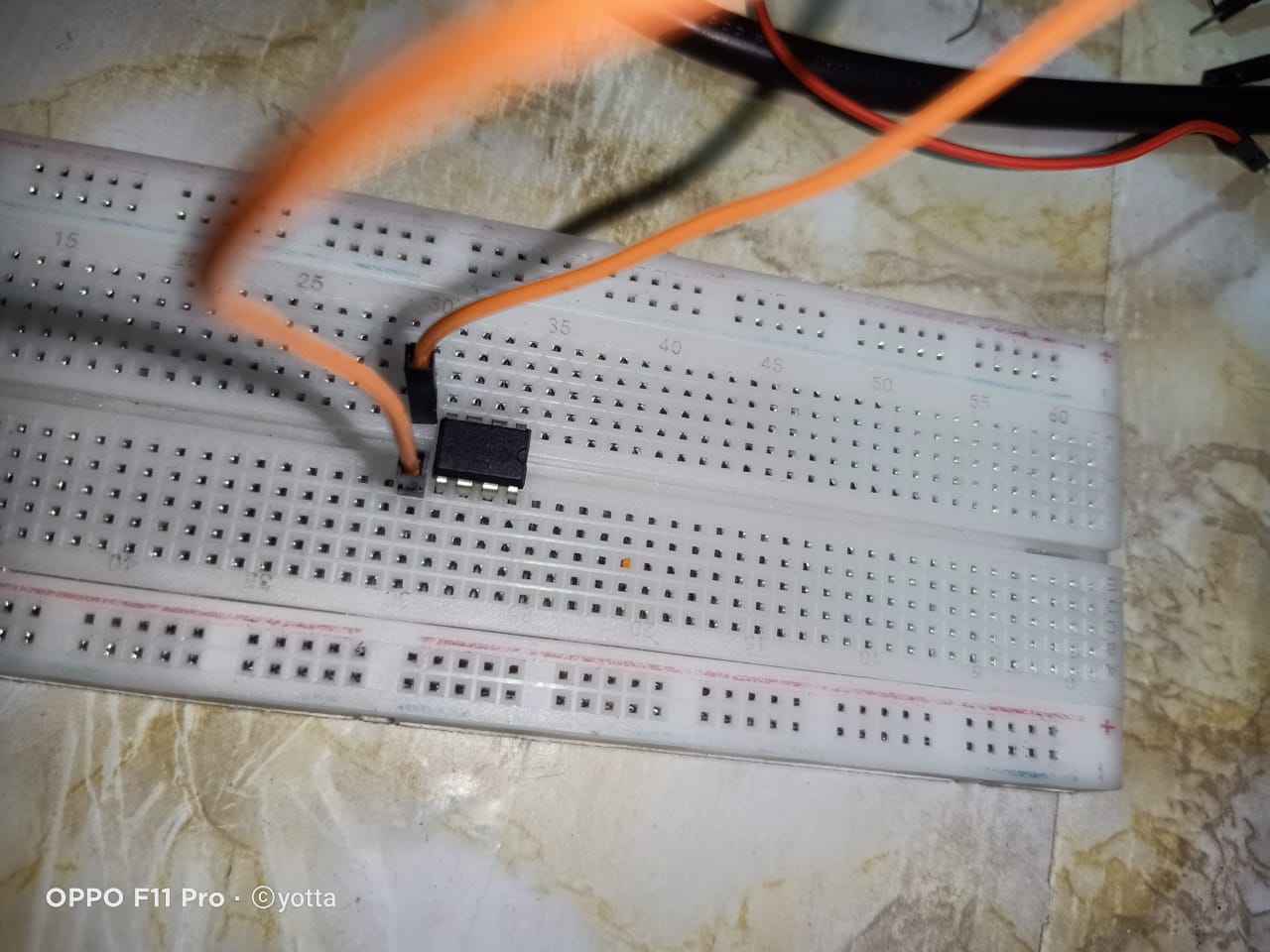
Step 5:
connect pin 6 with the jumper we connected in the previous step
Step 6:
connect pin 2 with the other side of the orange jumper
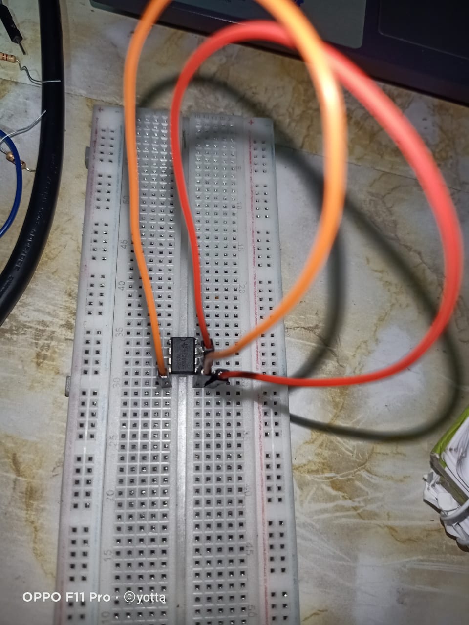
 Step 7:
connect another orange jumper in paraller with the previous one
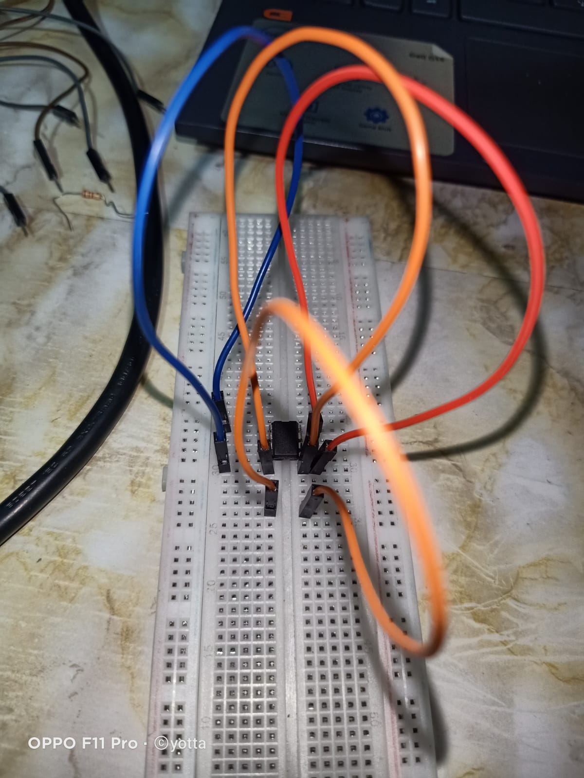
Step 8:
connect pin 8 with the last orange jumper as shown
Step 9:
connect pin 4 with the other side of the last orange jumper (we now connect the purple jumper)
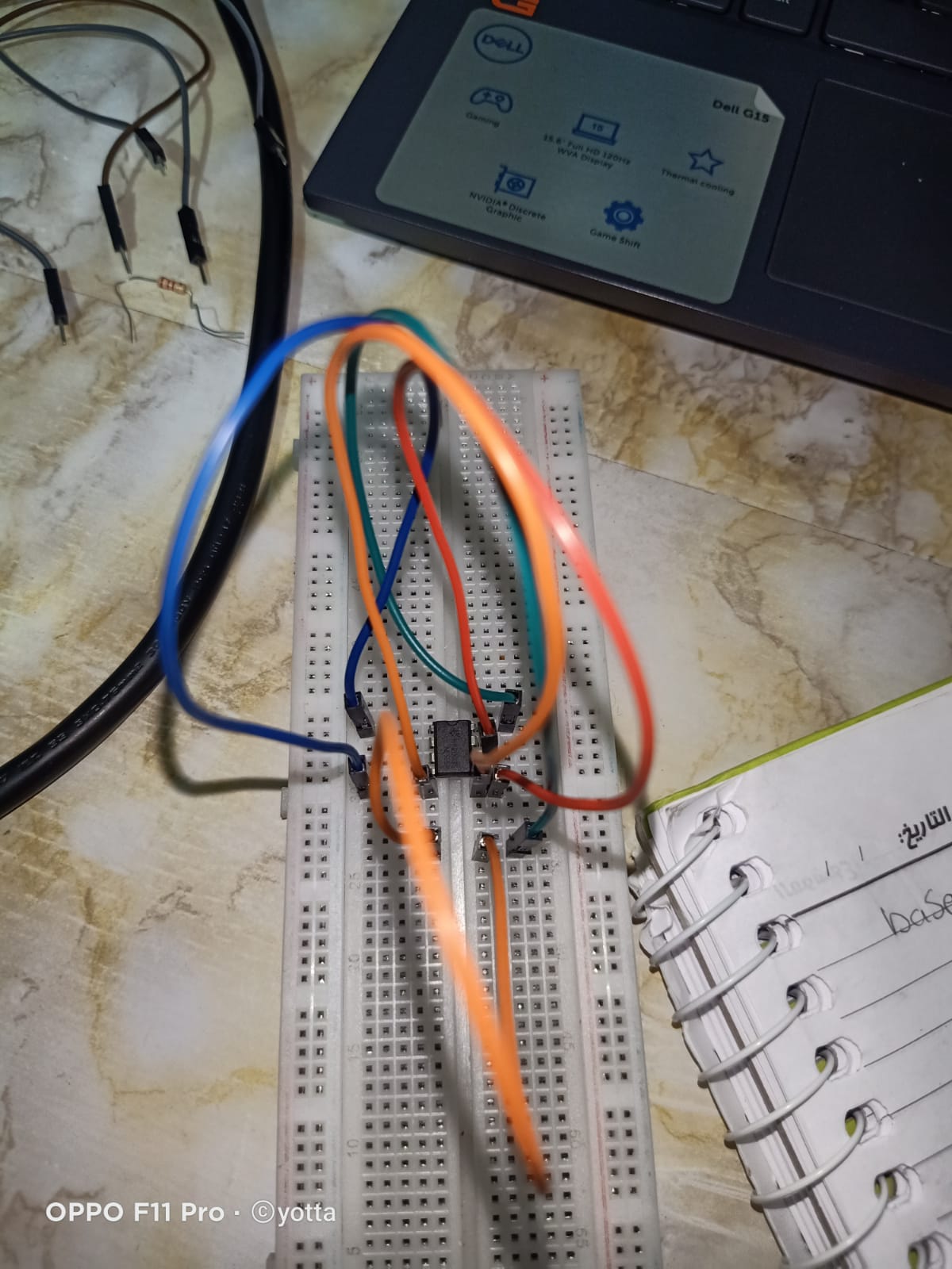
Step 10:
connect the 2.2k ohm resistor from pin 2 to pin 7
Step 11:
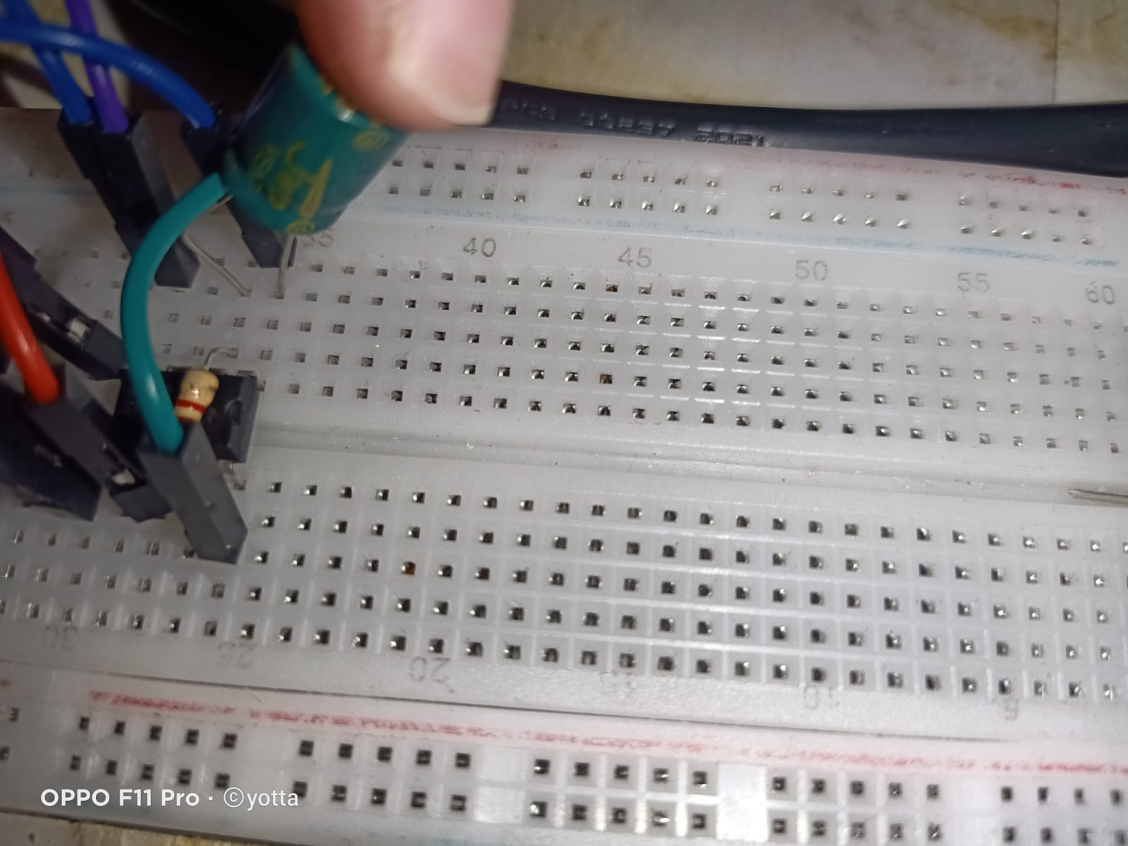
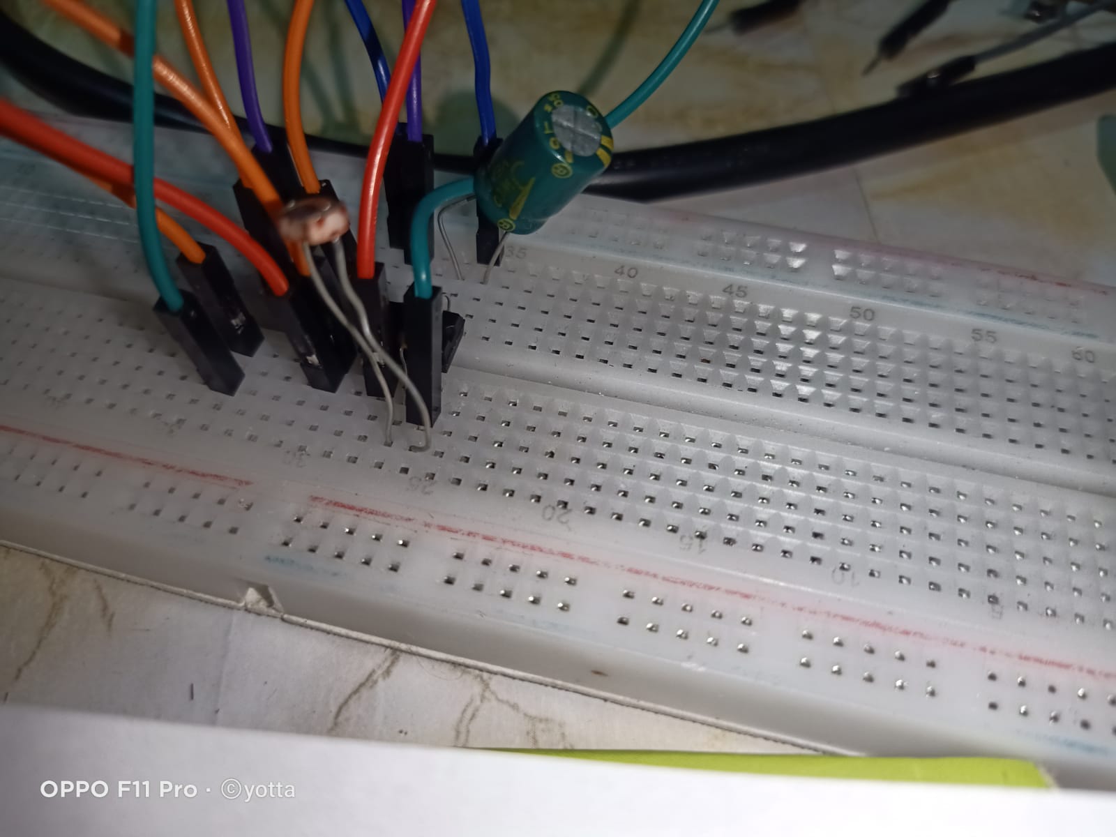
connect the capacitor the positive leg(taller)with pin 2 after the resistor , the negative leg with pin 1 as shown
Step 12:
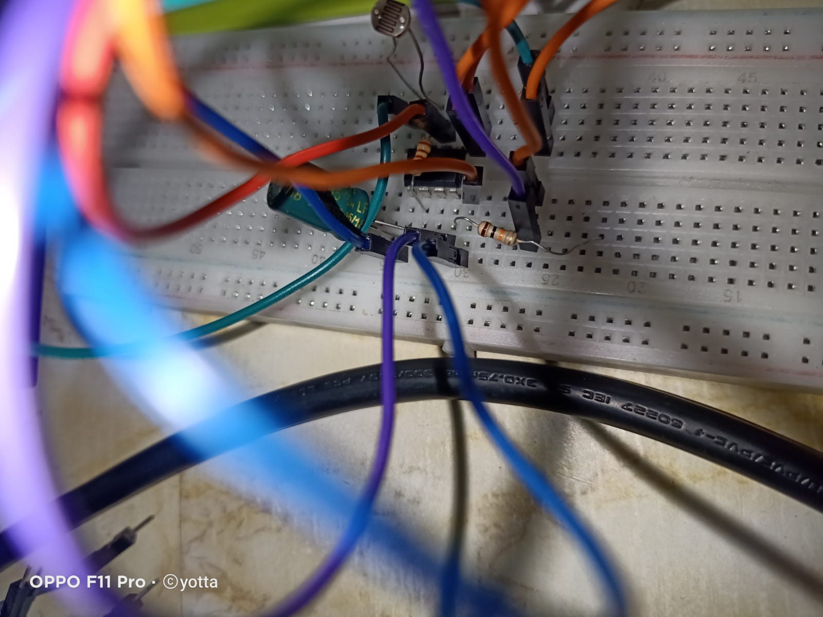
connect the LDR one leg with pin 7 and the other leg with pin 8
Step 13:
connect the 10 k ohm resistor one leg with pin 4 and the other in any position in the breadboard
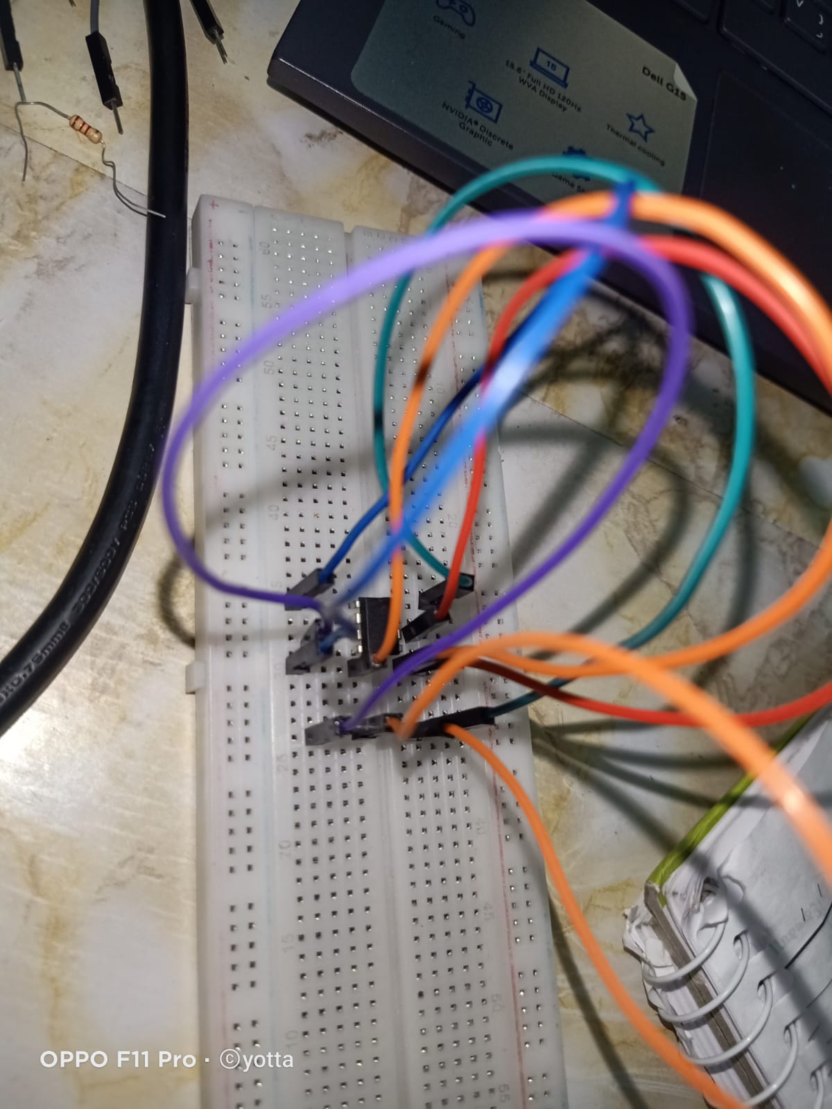
Step 14:
connect the speaker, the red wire with the other leg of the 10 k ohm resistor , the brown wire with pin 3 of the 555 timer
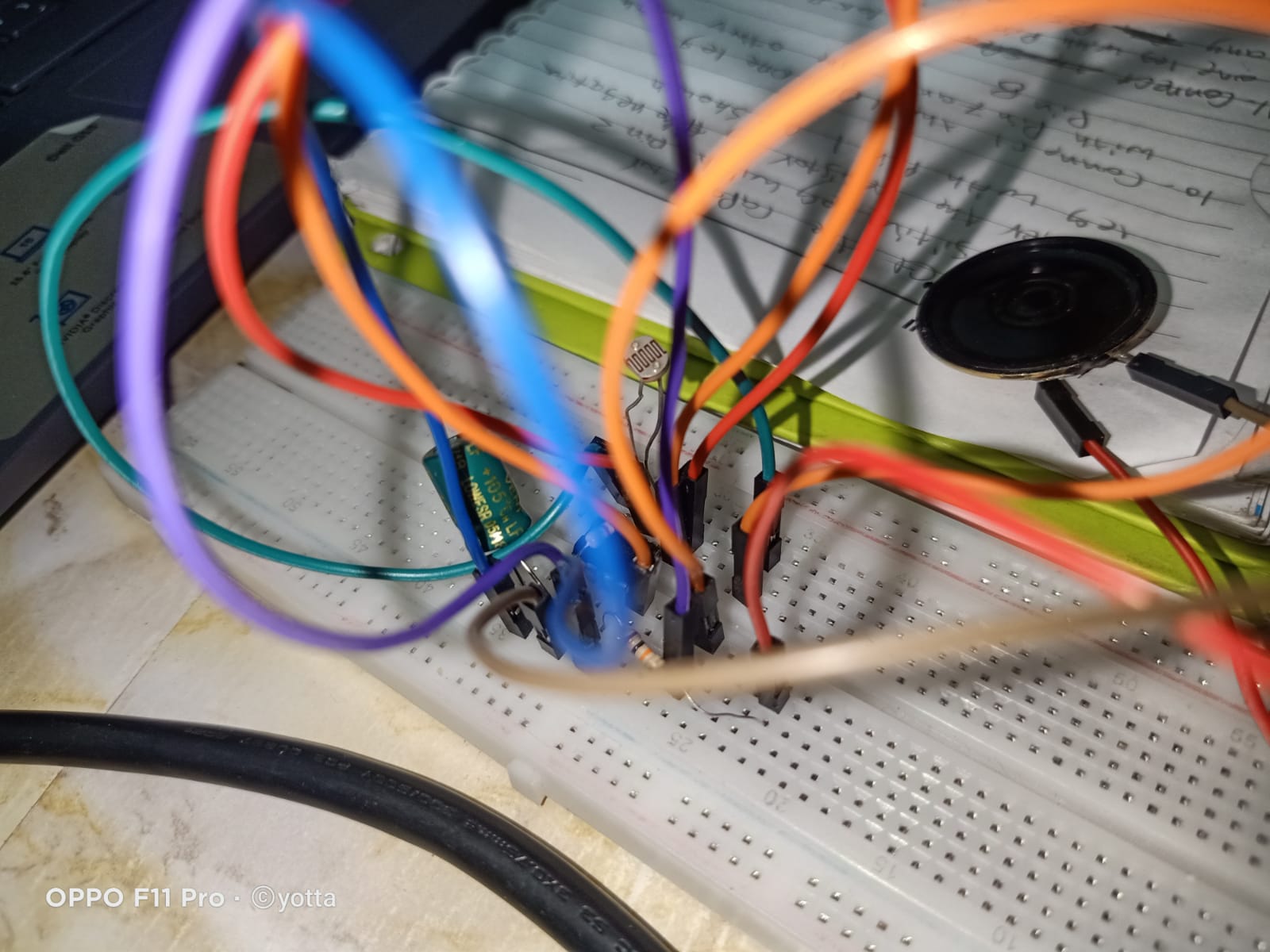
Step 15:
connect the battery pin 1 with the ground , pin 8 with the power