Idea:
Maker's marker is designed to gather the marker in one place to facilitate the instruction explaining process and provide the instructor with marker in a simple way. It consistes of two main parts. The inner box is responsible for storing the markers and must be inclined to roll the markers to the outer box, and the outer box store the marker when pressing on the outer box. then after releasing the inner box again, a holder attached to the inner box pushes the marker to stand up.
Components:
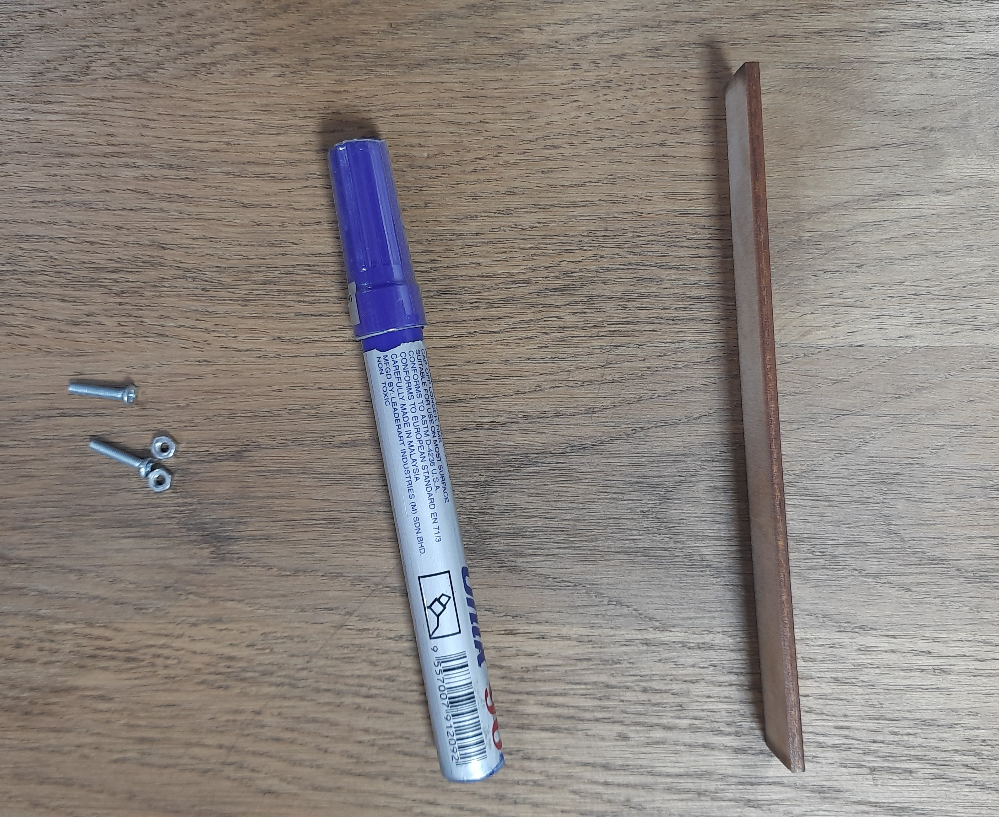
1. 3mm of wood
2. Marker
3. 2 screws and 2 nuts of 1mm diameter
Steps
Step 1:(Measure the dimensions)
Measure the dimentions of the marker to adjust the design on it, it turns to be 15 cm hight and a 1.75 cm diameter
The projects parts on solid works, which consists of two main parts. The inner box is responsible for storing the markers and must be inclined to roll the markers to the outer box. we
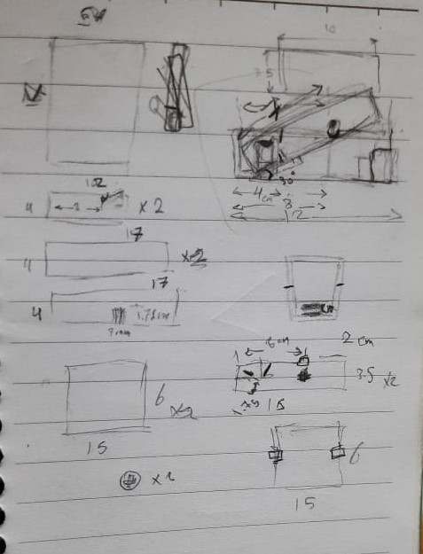
Step 2:(Drawing handsketches)
First, I tried to draw some simple handsketches to make a quicj imagination of how the design will be. I consider the inclined angle in the design and increased some measurements upon it and made a simple views of the main parts
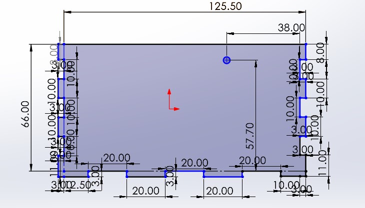
Step 3:(designing the inner box)
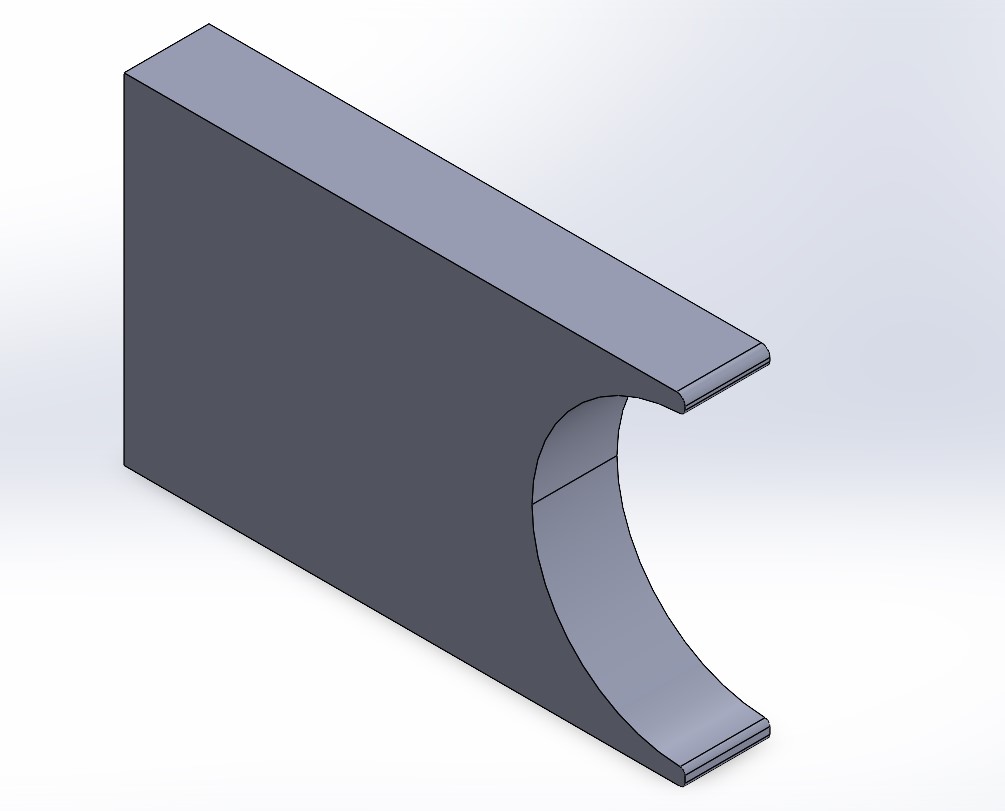
The projects parts on solid works, which consists of two main parts. The inner box is responsible for storing the markers and must be inclined to roll the markers to the outer box.
for the inner box, it must fit the marker with only some milimmeters difference, approximetly 16 cm in width and 2 cm in hight.
The inner box hight have to be double the raduis of the marker's width (approximetly 2cm)
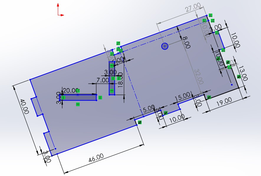
A) Base, the base of the inner box must not match the whole hight of the project in order to let a place for the markers to fall from the inner to the outer box(About double the diameter of the marker).
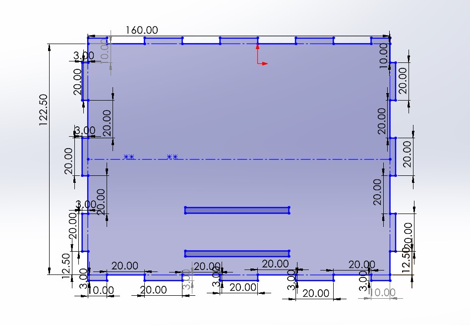
B) Side, The side of the box should implement some features in it beside containing the marker, which are fixing a holder that prevents the markers from falling, and fix a stander that makes the marker stand when the inner box is release. So it is designed in a dimensions of the whole box depth, and the double of markers approximete hight.
It also should have a hole to be fixed with screws with the outer box in order to allow the inner box to rotate inside the outer box.
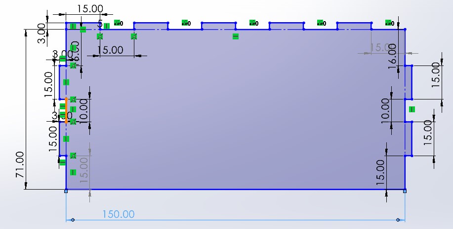
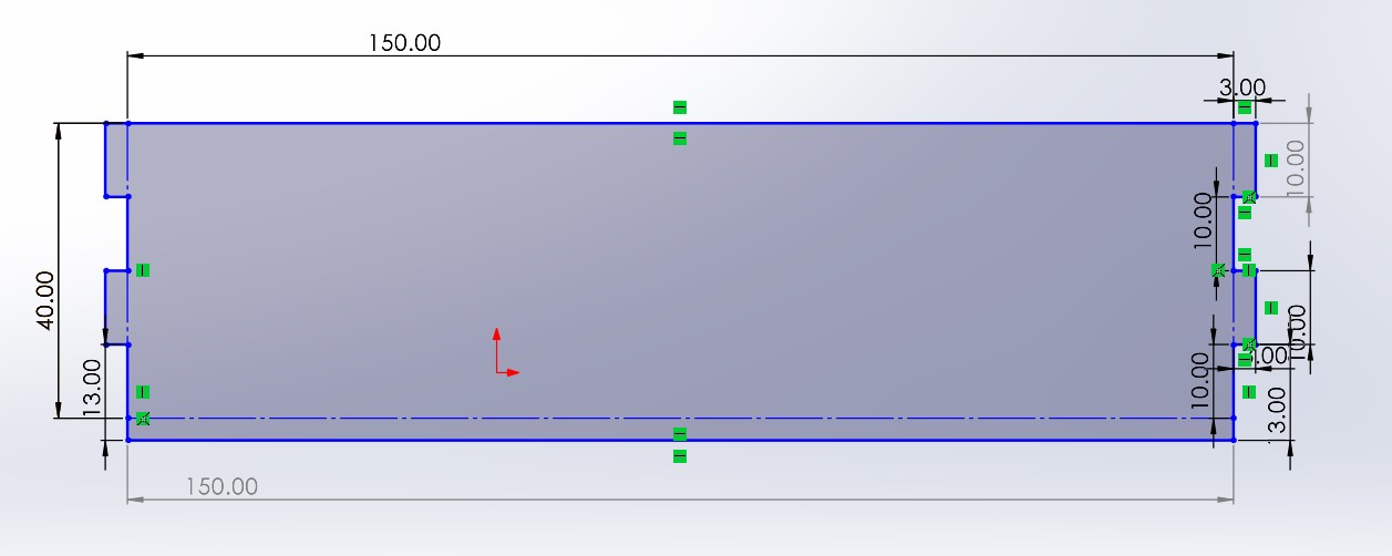
C) front, The front and back of the inner box just helps in fixing the box's sides, it also sets the limits to design the outer box upon it, it will take the approximete width of the markers and double of the approximete hight.
Step 4: Designing the outer box
A) base of the box, while deigning the base of the outer box; the increase of width of inner box due to the inclination angle must be put in consideration. I used Pythagorean theorem in order to calculate it as represented in the handsketch and applied that increase in depth of the base.
B) The front of the box, the front of the box will have a dimenstions of the fron of the inner box, but with an increase of 15 mm on the width of it. Also, the hight will be 3mm greater as the depth of the wood is 3mm.
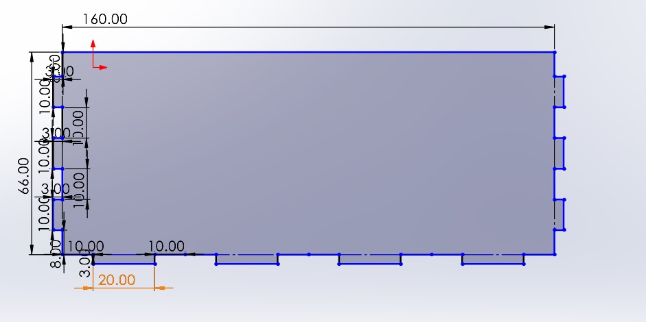
C) The Side of outer box, the side will be pretty simple and designed to fit in the base and front, but should have a hole adjuusted with the inner box for it to be attached to to incline.
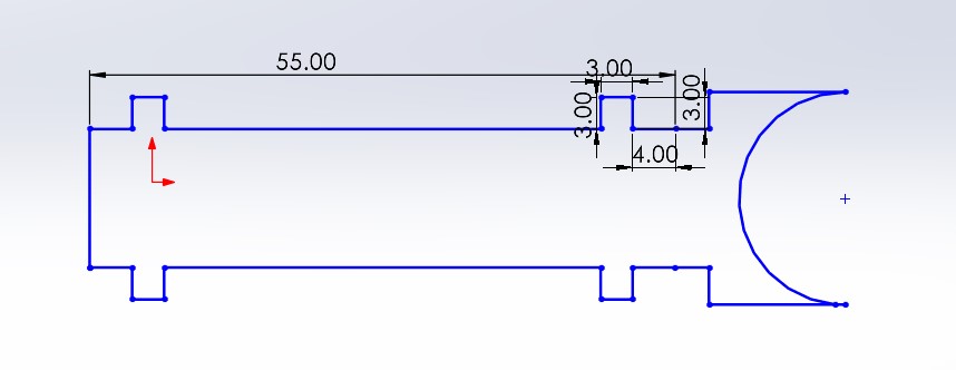
D) The marker holder of outer box, is designed in order to fix the marker in specific place in the box, it also has an circular ending with approximetly the same diameter of the marker in order to make it stand when the inclined angle increases.
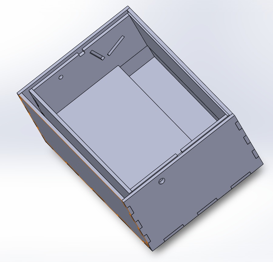
Step 5:(Assembly)
I grouped all this parts in an assembly to make sure that all dimensions fit
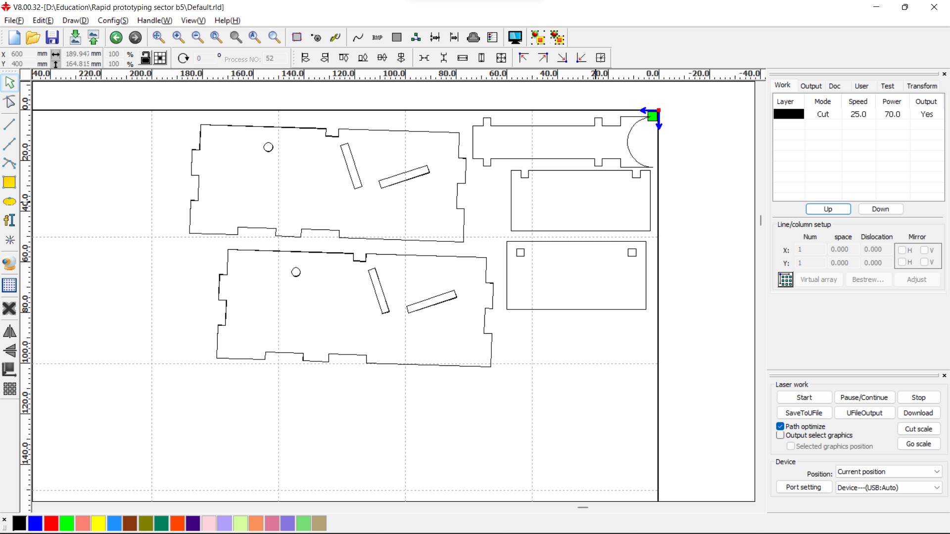
Step 6:(Preparing final files to cut)
Now, after finally designing all the parts, they are saved as a dxf file and grouped in RDworks software that is the CAM software the translates the dxf to G code for the machines to execute it.
Step 7:(Cutting)
After cutting the parts, I discovered that there was a part with wrong dimensions, so instead of cutting it again, I just used the manual option for the laser cutter in order to cut the part not wanted.
Step 8:(Testing)
After cutting the parts, It's the time to finally connect them and test the project first patch
the first patch was fine, but didn't achieve 100% of the trageted functionality... the marker was designed to stand upon releasing the inclined box, but it turns out that the stander is too light to raise the marker.
Step 9:(editing parts)
As told, the stander part that was responsible for raising the marker is not heavy enough to do so. As a solution I decided to make this part from metal, in order to match mass ratio required. I edited the part to have more with and thus more weight and exported it as stl file to be cut on the metal cutter
waiting to be cut this thur. 1st of Sep, and I will update the results soon!