Idea:
Hearing music is kind of joy, we really enjoy lestning to it and exchange some with other. What if you can make your own music!. It might seem too complex to make an insturment that makes music, but with some simple electronics everything becomes easier. Now let's make our blue organ, pack your list and be ready!
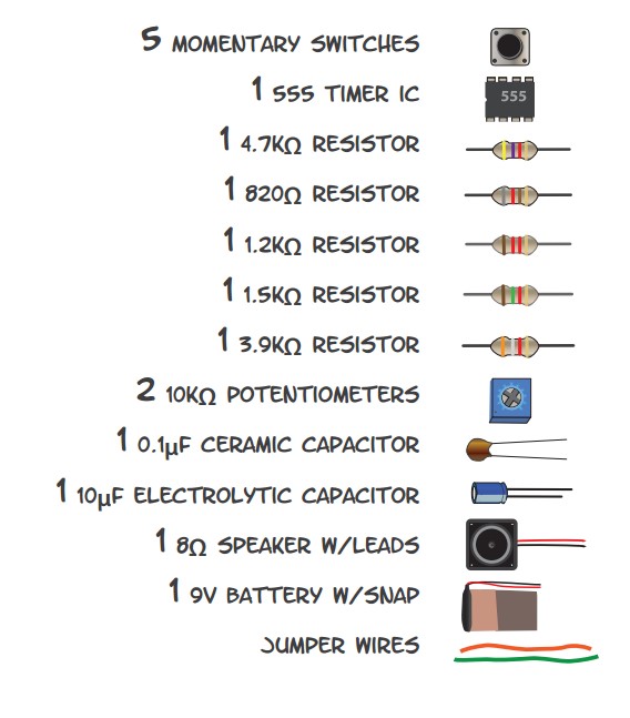
Components:
Steps
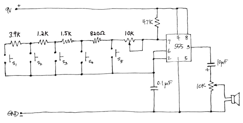
Step 1:(design the circuit)
For the piano to be pitch controlable, we used timer 555. The circuit is mainly a resistor ladder circuit, that depends on the values of the resistors to produce different sound of notes. As when the push button is pressed, it connect the trigger pin to the discharge pin with a certain value of resistance in between to produce the sound desired
Step 2:(Schematic and simulation)
One of the challenges was the value of the resitances, as thier value must have an observable difference in order for the notes to be different. As a solution I used Protus software to make a simulation for the circuit and tried to vary the resistor values untill I foound some values that could finally make a song. I tried the jingle bells song on it and it kinda worked :)
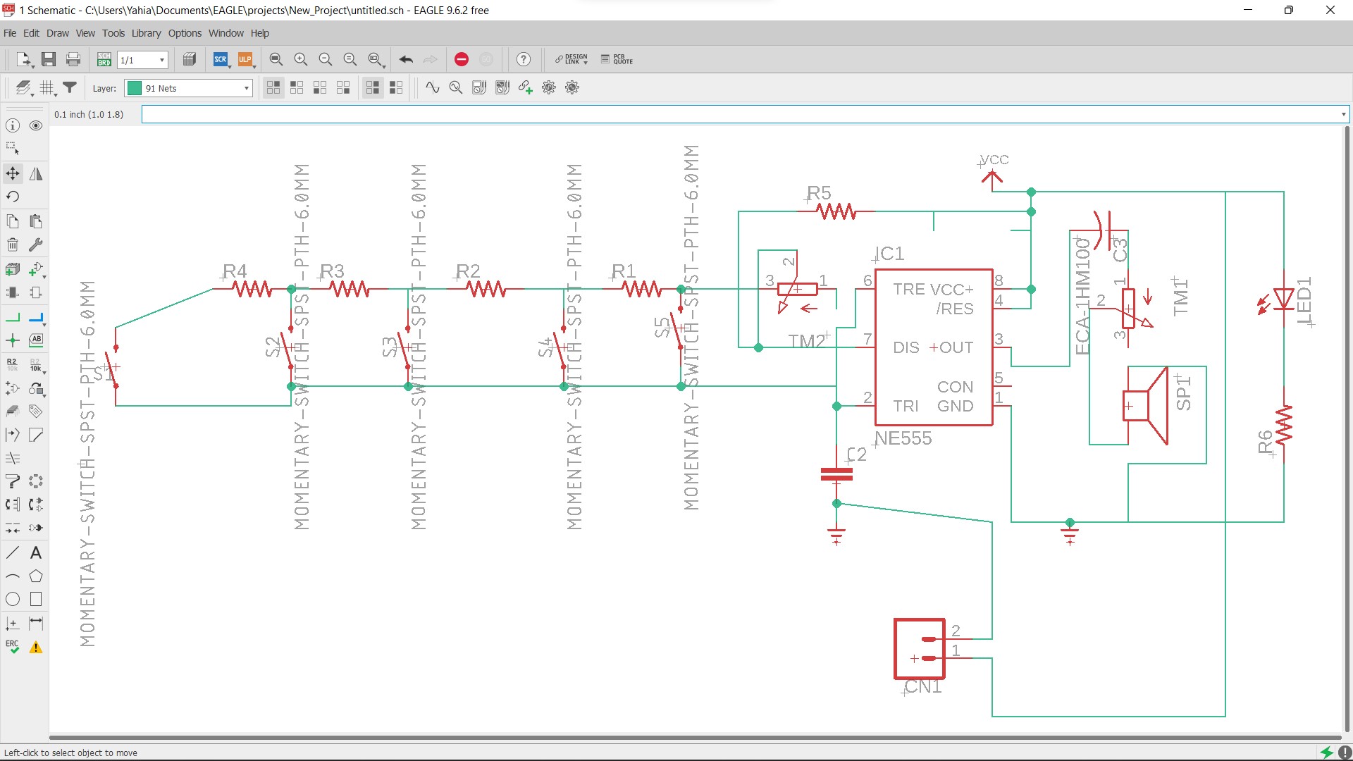
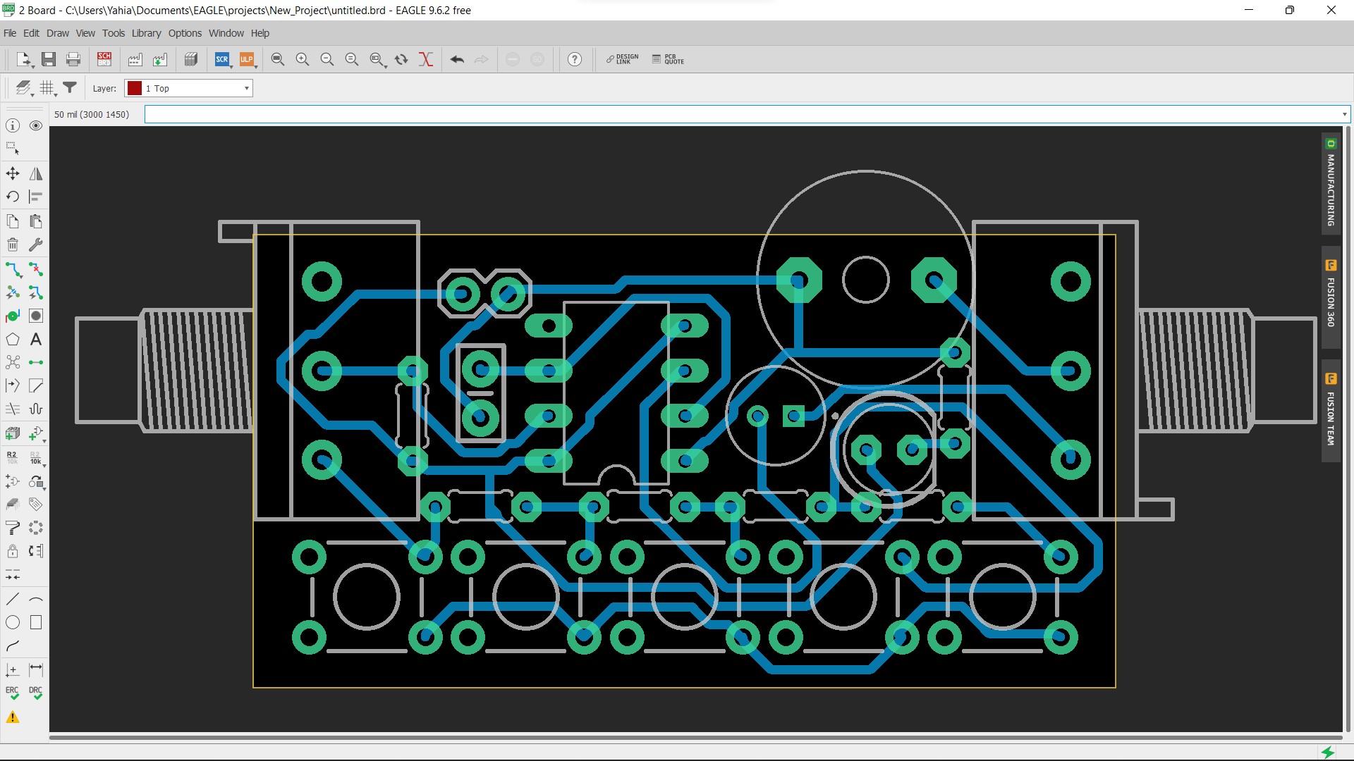
Step 3:(Designing the PCB board)
For the PCB design, I switched to eagle software as it has better PCB design control and libraries. First I drew the schematic digram of the circuit in order to apply it in the PCB wit the same connection. Then began to design the PCB of the circuit with some specifications, as the 2 variable resistors should be at the sides and the buttons should be infront and so on. The routing and design took some time but in the end it fitted perfectly with the smallest PCB board size achieved.
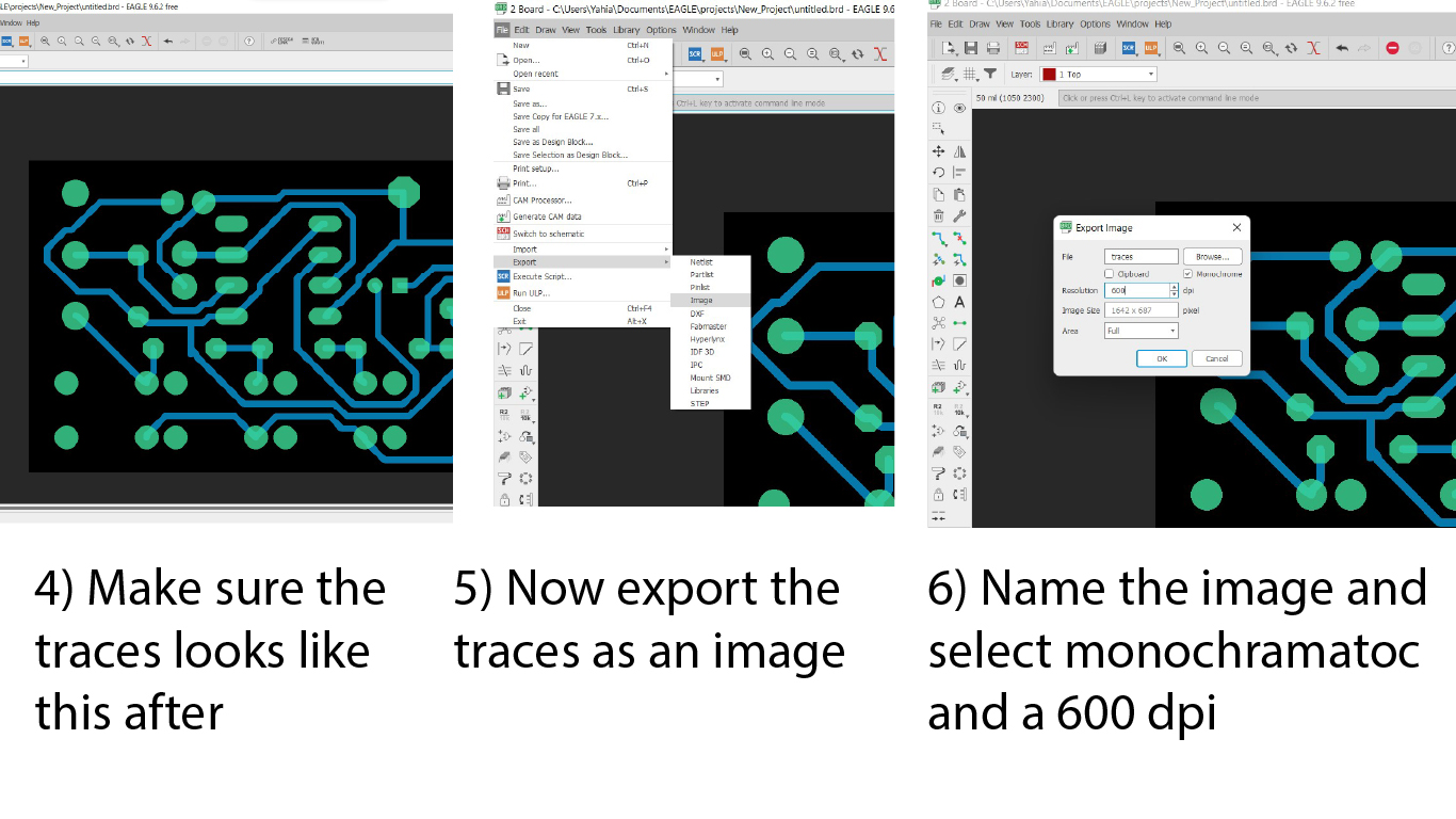
Step 4: (exporting the design)
Now after we designed the PCB circuit, we convert it to files to be prepared for machine files conversion:
The following images will explain the process

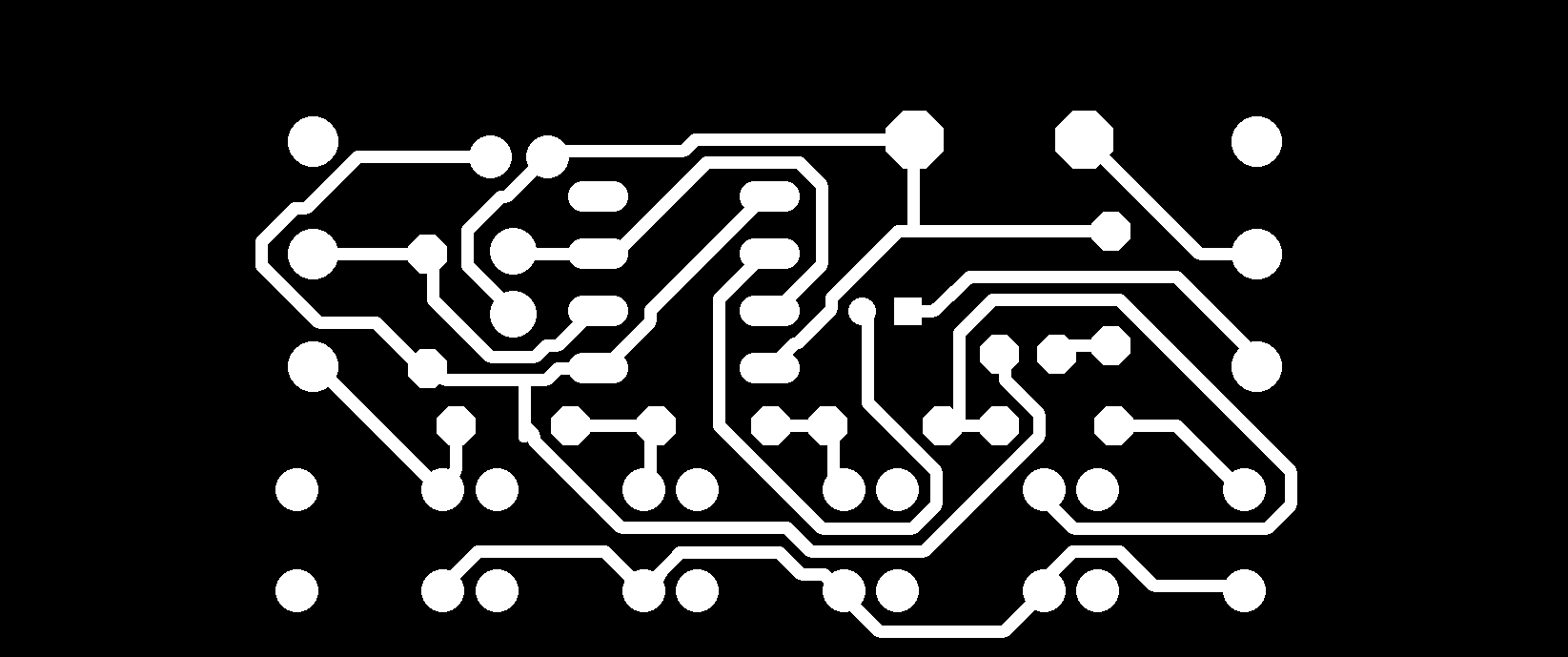
After applying all these steps, the exported image should look like this:
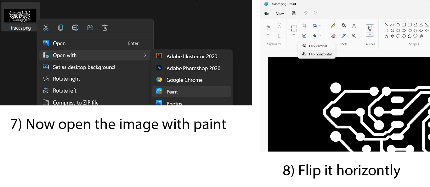
Then we open the images with Paint to edit it to be ready to be converted to machine code
Step 5:(Converting to machine files)
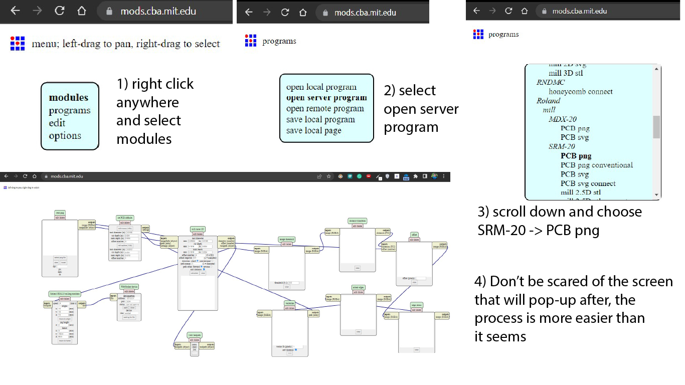
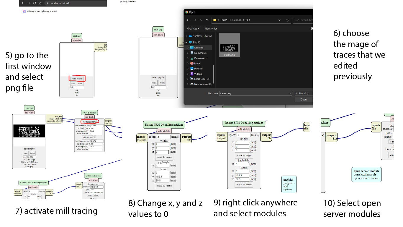
For the images to be converted to machine files, these images color difference must be turned into a vectors that the cnc will follow. Fab modules is an open sources website that provides this functionality, to open fab mods click here. So there are some steps with it shown in the images below:
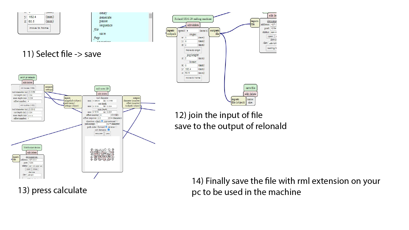
repeat the same exporting steps for dimensions and traces, here is a video for file to machine conversion for rest of the images:
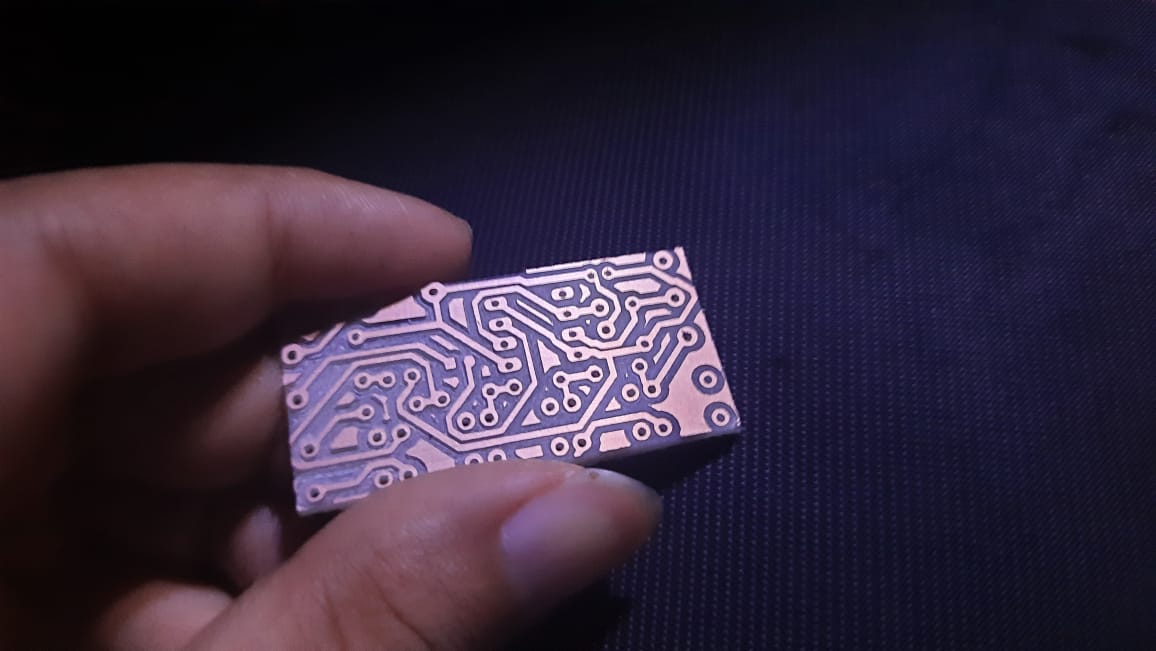
Step 7:(milling)
Now we can make the machine print the files, we first change the pont of the machine to the v-cut type and set the origins. Then we choose the file to but cut and start it. Here is a video when it works:
Step 8:(Testing)
Afer cutting, the final result was as shown in the image, I will try to weld the parts and update the news so stay tuned!